The entire contents of Advisory Leaflet 367 from the Minstry of Agriculture, Fisheries and Food (1961). Scanned using Optical Character Recognition – Will sort out the bloopers ASAP.
THE design and dimensions of the National single-walled hive, described here, follow closely the revised specification issued by the British Standards Institution (British standard 1300: 1960). All the units are fully interchangeable with those constructed to the patterns given in earlier editions of this leaflet.
General Description
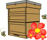
The hive consists basically of-a floor (Fig. 2) provided with an entrance block, one or more deep boxes {Fig. 3a) serving as a brood chamber, a crownboard (Fig. 4) and a roof (Fig. 5). For the storage of surplus honey, “supers” in the form of deep orshallow boxes, or section racks (Fig. 6) are added above the brood cham- -ber. Queen excluders made to B.S. specification are available from bee appliance dealers for insertion be- tween brood chamber and supers.
The deep box is designed to take up to eleven 14 in. X 8! in. frames with 1-! in. lugs. The shallow box holds eleven shallow frames 14 in. x 5-! in. with standard narrow spacing, or nine frames with wide spacing. The recessed end walls in both types of box provide excellent handholds for lifting individual units, or for moving the whole hive when the units are fixed together for transporting from one site to another. r
The section rack, taking thirty-two sections each 4-! in. X 4! in., has D-shaped finger grips cut into the thickness of the walls.
The ro(jf is designed to provide a It in. ventilated, bee-tight air space above the crownboard; it is equally suitable if a canvas quilt is used in- stead of a crownboard. The sides of the roof are deep enough to pre”ent it from blowing off in windy weather.
The floor is designed to be rever- sible to provide a full width entrance ! in. deep on one side or i in. deep on the other. It should be supported clear of the ground, either on four bricks or on some form of stand. The simple type of stand illustrated here (Fig. 7) has an alighting board which fits flush against the front of the floor; the side runners are cut away to form handholds.
The deep and shallow boxes may be placed on the floor with the frames lying either parallel, or at right angles to the entrance (“warm way” or “cold way” respectively). The bee- space is below the frames in each unit.
The section rack, like the deep and shallow supers, fits flush on the unit below it. A bee-space under the sec-
tions is provided by the transverse strips which support them in the rack.
Specification
FLOOR The dimensions of the floor are 18l in. X 18l in. x 2 in. The floor- boards are of timber -! in. thick, with tongued and grooved or lapped joints, grooved i in. into side rails -! in. thick and 2 in. deep, the grooves being i in. from one edge and ~..,in. from the other; the back is closed on each side with a strip of wood, one i in. X i in. X l6i in. and the other i in. X i in. X l6i in., nailed on at opposite ends.
ENTRANCE BLOCK The entrance block is 16! in. long and a bare i in. square in cross section with a 5 in. x * in. central cut-away on one face. Using the floor with its deeper side uppermost, the block can be inserted to give either a reduced entrance to the hive or to close it completely. To prevent the block being pushed in beyond the front wall of the hive, it is recommended that a staple should be driven into the inner face of each of the side rails of the floor, i in. from the front end, to leave a projecting loop of about i in.
BROOD CHAMBER The outside lateral dimensions of the brood chamber are ISk in. X ISi in. ; the depth is Si in. All four walls are made of i in. finished tim- ber. The end walls are 17 in. X 7 * in. and are let into the side walls to a depth of * in., 1 in. from each end. TQis I in. space between the outside surface of each end wall and the end of the side walls is closed with two fillets, one at the top and one at the bottom. The top fillet is rebated on the inside * in. deep from the top edge, leaving a shoulder t in. wide. This rebate forms part of the recess
which encloses the ends of the frame lugs. The bottom fillet is rebated on the underside to a depth of t in. leaving a shoulder of! in. This pro- vides the bee-space above the lugs of the frames in any box below. The upper surface of the bottom fillet is chamfered to shed the rain.
The frame lugs are raised above the rebates of the top fillets on run- ners. These runners are set with their top edges 1~ in. below the top edges of the side walls of the box.
A good method of constructing the ends of the box is illustrated in Fig. 3a, where the top and bottom fillets are attached to the side walls by tenon joints. These joints should not be cut less than i in. from the top and bottom edges of the walls respective- ly. Further details of the construc- tion are shown in Fig. 3b.
SHALLOW SUPER
The dimensions and construction are the same as for the brood cham- ber except that the depth is Si in.
The depths specified for the brood chamber and the shallow super provide a bee-space of i in. below the frames, which is the maximum that can be permitted if the building of burr comb by the bees is to be avoided. This allows for a slight shrinkage of the wood. It is ~ost important to use well-seasoned timber to ensure that the bee-space is not reduced below! in. by excessive shrinkage in the width of the boards after they have been cut to the specified size.
CROWNBOARD The dimensions of the crownboard are 18 in. X 18 in. Recommended materials are knot-free, well-sea- soned softwood at least i in. thick, with rebated or tongued and grooved joints, or resin-bonded plywood atleast 5 mm. thick. A t in. bee-space is provided on each side by framing
-with four strips of softwood 17i in. X ! in. X t in. The strips are so arranged that at any corner the joint on one side is at right-angles to that on the other (Fig. 4). Alternatively, the board may be rebated into a frame of such thickness that a t in. bee-space is provided on each side.
‘ The board should have two openings 11\- in. x 3 in. adapted to receive Porter bee e-scapes, one centrally situated and the other parallel to it, with its centre 3 in. from the edge of the board.
ROOF The inside measurements of the roof are 18! in. X 18! in. X 5! in. The top boards should be not less than i in. thick, and the side walls not less than -!- in. thick. The corners should be lock jointed and nailed both ways. (If halved joints are preferred, the timber should be at least i in. thick). The roof should be covered with non-rusting sheet metal or other waterproof material, .extending at least 1! in. down the side.
Four strips of wood 18 in. long and 1! in. x! ifucross-section, are fixed round the top inside to give a head- space of 1! in. above the crown- board. Ventilatio~ holes! in. in dia- meter are bored centrally through the sides of the roof and spacing strips, and backed with perforated zinc or non-rusting wire mesh (see Fig. 5).
SECTION RACK The outside dimensions are 181 in. X 181 in. The side walls are made of two pieces of -!- in. wood 181 in. X 4-f1r in., lock jointed and nailed both ways to end walls of i in. wood 18i in. X 4* in., giving internal dimensions of 171 in. X 161 in. X 4* in. The rack takes thirty-two sections, each 4! in. X 4! in., in four
rows of eight. The sections are held tight by a follower board, 17 in. x 4:!in. X iin., supported by two springs suitably shaped from:! in. wide strip spring steel. These springs may be obtained from appliance dealers if desired.
The sections rest on five strips, two 181 in. X l-k in. x:! in., and three 181 in. X 1 in. x:! in., the wider ones being used at the sides, equally spaced across the bottom of the i in. walls and running parallel to the-! in. walls. The strips are interspaced by four pieces of wood 3:! in. X t in. x :!in. at one end, and four pieces 3:! in. X 2 in. x:! in. at the other, the latter projecting ..li in. inside at the follower board end to prevent the bees entering the space behind the board.
The strips and interspacing pieces provide a:! in. bee-space below the sections, increasing the overall depth of the rack to 4-& in. D-shaped finger grips are cut in the two end walls.
HIVE STAND
See page 2, and Fig. 7.
Assembly of Hive Parts When assembling the hive parts to form the individual units, it is strongly recommended that a good quality waterproof glue ( e.g., cold water casein glue) should be applied to the joints, particularly to those of the deep and shallow boxes. For additional strength and durability the parts should also be nailed to- gether, preferably with rust-proofed nails.
This advice applies equally to the assembly of hives from sets of parts bought ready-made from bee ap- pliance dealers.
FLOOR Fit the tongued and grooved, or rebated floorboards into the groovesof the side rails. Secure with nails clOven in from the outside of the side rails. Nail on the back strips, one on each side at opposite ends.
DEEP AND SHALLOW BOXES Fit the end walls into the grooves in the side walls and ¥il through the grooves, making sure that the end walls finish t in. short of the sidewalls at the bottom and t~at the runners for the frame lugs lie * in. below the top edges of the side walls. Fit and nail the four rebated end fillets, the chamfered ones at the bottom.
SECTION RACK Assemble and nail the four lock jointed walls. Turn upside down to assemble and nail the five cross strips (one wide strip at each side) and their eight interspacing pieces (with the four wide ones all at the same end of the rack). The follower board and springs are inserted at this end.
ROOF Assemble and nail the sides. Fix the four strips inside round the top.
Nail on the top boards, making sure that the assembly is square. Fit the waterproof cover and secure it with galvanized tacj(s round the sides. Bore a i in. hole centrally in each side, passing through the cover, side wall and inside strip. Back the holes with perforated zinc or wire mesh having apertures not greater than 9 .
d.t1 .
7J4 1ll. lame er or 8 1ll. square.
TIMBER AND FINISH The B.S. specification requires that the timber used for making external parts of hives shall be western red cedar, free from signs of decay or insect attack and properly air-dried. Knots, if sound and tight, are per- mffisible provided their diameter ?oes not exceed one quarter of the width of the timber and that no knot exceeds t in. diameter.
No protective finish ,is needed for western red cedar, but for hives made of softwoods other than cedar it is best to use a good brand of colo:?rless preservative fluid. Paint or dark- coloured wood preservatives are not recommended.
MINISTRY OF AGRICULTURE, FISH~RIES AND FOOD, Whitehall Place, London, S. W .1 (Revised) January 1961
(Reprinted) May 1961
@ Crown copyright 1961
Printed in England by Staples Printers Ltd., Kettering and published by
HER MAJESTY’S STATioNERY OFFICE Price Jd. net –
— (1211) 2350/4046 K40 7161 Gp.3S2
– 24-9999

